
Page 14 - Prospekt
P. 14
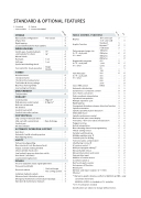
STANDARD & OPTIONAL FEATURES
S : Standard
– : Not available
SPINDLE
Main spindle configuration
ZF gear box
Rigid tapping
O : Option
C : Contact GOODWAY
    FANUC CONTROL FUNCTIONS
  Two-speed
S Display O
S Graphic function O
S Part program storage size O Oi -TF : each path
O 31i : total
O
S Registerable programs
C Oi -TF : each path S 31i : total
Tool offset pairs
Oi -TF : each path S 31i : total
O
S
O Servo HRV control
O Automatic data backup
8.4" color LCD S – 10.4" color LCD – S Standard S –
                                 Cs-axis & disk brake for main spindle
Dynamic*1 512K bytes 1M bytes 2M bytes 4M bytes 8M bytes 400
O S S – – S O O – O – O S – O S – O – S
              WORK HOLDING
Solid 3-jaws chuck & hydraulic solid cylinder for chuck
Manual chuck
Hard jaws
Soft jaws
Special work holding chuck
Foot switch for chuck operation 8-station turret
12-station turret
12-station live tooling turret
Tool holder & sleeve package
Dual-Face Turning Holder
Live tooling tool holders
Tool presetter
COOLANT
Coolant pump High-pressure coolant system
Roll-out coolant tank
Oil skimmer
Coolant level switch
Coolant intercooler system
CHIP DISPOSAL
Chip conveyor with auto timer
Chip cart with coolant drain
Coolant gun
Oil mist collector
Auto door
15" 18"
1 set
1 set
Single Double
O O
1,000
4,000
99
128 S– 200 OO 400 –O 499 –O
                                                                                 TURRET
                                999 2000 HRV 3
– O – O S S S S O O S S S S S S S S S S S S S S S S O O S S S S S S S S O O S S S S S S S S S S S S S S O S S S O O S O S S S S S S S S S S S S S S S S
                                           MEASUREMENT
               O
Synchronous / Composite control
Inch / metric conversion
Polar coordinate interpolation
Cylindrical interpolation
Multiple repetitive cycle
Rigid tapping
Unexpected disturbance torque detection function
Spindle orientation
Spindle speed fluctuation detection
Embedded macro
Spindle synchronous control
                      5 Kg/cm2 S 20 Kg/cm2 O
S O O O
                                                                                                    S Run hour and parts count display
       Tool radius / Tool nose radius compensation
Polygon turning
Helical interpolation
Direct drawing dimension programming
Thread cutting retract
Variable lead threading
Multiple repetitive cycle II
Canned cycles for drilling
Tool nose radius compensation
S Chamfering / Corner R
S Al contour control I
S Multi part program editing*2
S Manual handle retrace
O Manual intervention and return S External data input
       Rear discharge O
O O
O
                                         AUTOMATIC OPERATION SUPPORT
                      Automatic load & unloading system —
Parts flipping device —
SAFETY
Fully enclosed guarding
Door interlock ( incl. Mechanical lock )
Impact resistant viewing window
Chuck cylinder check valve
Low hydraulic pressure detection switch
Over travel ( soft limit )
Addition of custom macro
Increment system C
Run hour & parts counter
Auto power-off function
RS-232 port
Memory card input / output ( CF + USB )
MANUAL GUIDE i is standard on 31i controller. *2 10.4" LCD option needed
Specifications are subject to change without notice.
                                                                                                                                Load monitoring function S
OTHERS
Tri-color operation status signal light tower S
                              Florescent work light
Electrical cabinet
Complete hydraulic system
Advanced auto lubrication system
Emergency maintenance electrical part package
S
Heat exchanger S A/C cooling system O
Ethernet
                                       S
S *1 Dynamic graphic display conflict to MANUAL GUIDE i , only S can choose one to have.
                            Operation & maintenance manuals S
       GV-780
31i Oi - TF
